03. Estimating TTC with a Camera
Estimating TTC with a Camera
ND313 C03 L02 A04 C23 Intro
Measuring TTC without distance
Monocular cameras are not able to measure metric distances. They are passive sensors that rely on the ambient light which reflects off of objects into the camera lens. It is thus not possible to measure the runtime of light as with Lidar technology.
To measure distance, a second camera would be needed. Given two images taken by two carefully aligned cameras (also called a stereo setup ) at the same time instant, one would have to locate common points of interest in both images (e.g. the tail lights of the preceding vehicle) and then triangulate their distance using camera geometry and perspective projection. For many years, automotive researchers have developed stereo cameras for the use in ADAS products and some of those have made it to market. Especially Mercedes-Benz has pioneered this technology and extensive information can be found here : http://www.6d-vision.com/ . With more advanced ADAS products and with autonomous vehicles however, stereo cameras have started to disappear from the market due to their package size, the high price and the high computational load for finding corresponding features.
Despite those limitations of the mono camera, let us see if there is a way to compute TTC without the need to measure distance. Let us consider the constant velocity motion model we introduced in a previous section of this course and think about a way to replace the metric distances d with something the camera can measure reliably, such as pixel distances directly on the image plane. In the following figure, you can see how the height H of the preceding vehicle can be mapped onto the image place using perspective projection. We can see that the same height H maps to different heights h_0 and h_1 in the image plane, depending on the distance d_0 and d_1 of the vehicle. It is obvious that there is a geometric relation between h , H , d and the focal length f of the pinhole camera - and this is what we want to exploit in the following.
.png)
Let us take a look at the following set of equations:
.png)
In (1) we use the focal length of the camera and a distance measurement d_0 performed at time t_0 to project the height H of the vehicle onto the image plane and thus to a height h_0 in pixels. The same is done at time t_1 , leading to a projected height h_1 .
In (2), we compute the ratio of the relative heights h_0 and h_1 . As both H and f are cancelled out, we can observe a direct relation between relative height h and absolute metric distance d . We can thus express the distance to the vehicle d_0 as the product of d_1 and the ratio of relative heights on the image plane.
In (3), we substitute d_0 in the equation for constant velocity and solve for d_1 , which is now dependent on the constant relative velocity v_0 , on the time between measuring d_0 and d_1 and on the ratio of relative heights on the image plane.
In (4), the TTC is computed as the ratio of remaining distance to impact, which is d_1 , and the constant velocity v_0 . As we can easily see, the TTC now only consists of \Delta t , h_0 and h_1 . Thus, it is possible to measure the time to collision by observing relative height change on the image sensor. Distance measurements are not needed and we can thus use a mono camera to estimate the time-to-collision by observing changes in relative height (also called scale change ) directly in the image.
The Problem with Bounding Box Detection
In the figure below, a neural network has been used to locate vehicles in successive images of a monocular camera. For each vehicle, the network returns a bounding box, whose width and/or height could in principal be used to compute the height ratio in the TTC equation we derived in the last section.
When observed closely however, it can be seen that the bounding boxes do not always reflect the true vehicle dimensions and the aspect ratio differs between images. Using bounding box height or width for TTC computation would thus lead to significant estimation errors.
.jpg)
In most engineering tasks, relying on a single measurement or property is not reliable enough. This holds especially true for safety-related products. Therefore, we want to consider wether there are further properties of vehicles and objects we can observe in an image.
Using Texture Keypoints Instead
Instead of relying on the detection of the vehicle as a whole we now want to analyze its structure on a smaller scale. If if were possible to locate uniquely identifiable keypoints that could be tracked from one frame to the next, we could use the distance between all keypoints on the vehicle relative to each other to compute a robust estimate of the height ratio in out TTC equation. The following figure illustrates the concept.
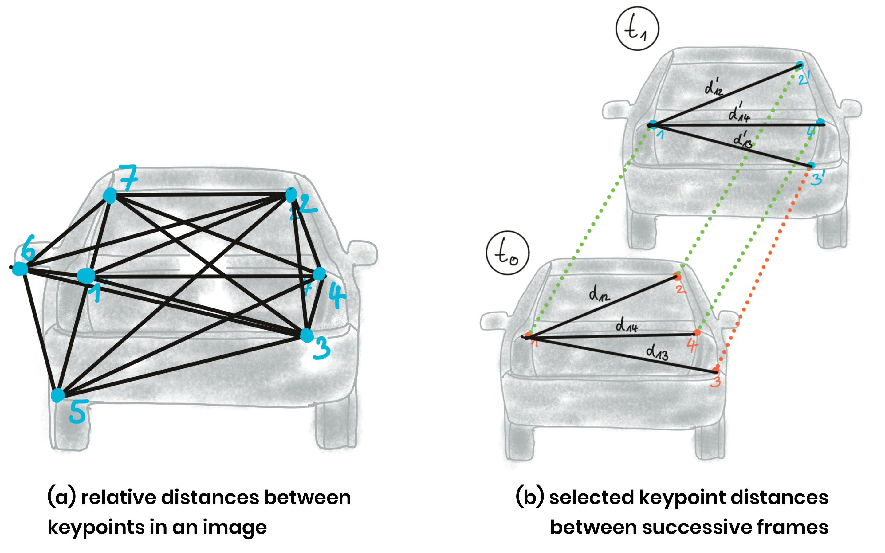
In (a), a set of keypoints has been detected and the relative distances between keypoints 1-7 have been computed. In (b), 4 keypoints have been matched between successive images (with keypoint 3 being a mismatch) using a higher-dimensional similarity measure called descriptor (more about that in the next lesson). The ratio of all relative distances between each other can be used to compute a reliable TTC estimate by replacing the height ratio h_1 / h_0 with the mean or median of all distance ratios d_k / d_k' .
The following figure shows several example of relative distances between keypoints as an overlay over a highway driving scene (only the preceding vehicle is highlighted).
.png)
Computing TTC from Relative Keypoint Distances
In the code examples in this course, matching keypoints between images are packaged into an OpenCV data structure called
cv::DMatch
. The structure elements we will be using in this course are
queryIdx
, which is the index of a keypoint in the current frame, and
trainIdx
, which is the index of the matched keypoint in the previous frame.
All matched keypoints are stored in a dynamic list, which is then passed to a function called
computeTTCCamera
, which returns the time-to-collision for each object in the scene. Let us take a look at this function in the following.
Exercise
ND313 C03 L02 A05 C23 Quiz
Imagine a set of associated keypoint between two successive frames which contain a large number of mismatches. Computing the mean distance ratio as in the function we just discussed would presumably lead to a faulty calculation of the TTC. A more robust way of computing the average of a dataset with outliers is to use the median instead. In the code below, replace
meanDistRatio
with a variable
medianDistRatio
and do not forget to consider both an even and an odd number of values in the vector
distRatios
.
Workspace
This section contains either a workspace (it can be a Jupyter Notebook workspace or an online code editor work space, etc.) and it cannot be automatically downloaded to be generated here. Please access the classroom with your account and manually download the workspace to your local machine. Note that for some courses, Udacity upload the workspace files onto https://github.com/udacity , so you may be able to download them there.
Workspace Information:
- Default file path:
- Workspace type: react
- Opened files (when workspace is loaded): n/a
-
userCode:
             export CXX=g++-7


              export CXXFLAGS=-std=c++17